Civil Engineering
0 ContainersFiles in Civil Engineering
Order by
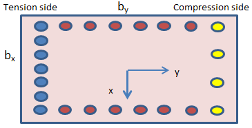
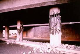
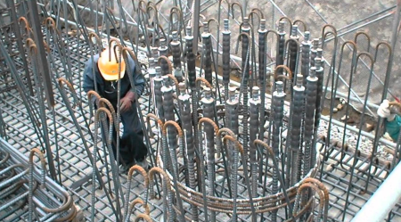
Abutment Column Design
Short Description:

Submitted By:
Last Modified
24 Mar 2012
Downloads:
195
Rating:

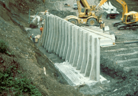
ACI 318 08 Design of Retaining Wall with Counterfort
Short Description:
Submitted By:
Last Modified
16 Apr 2014
Downloads:
466
Rating:

ACI 318-08 Column Design for Axial Load only
Short Description:
Submitted By:
Last Modified
16 Apr 2014
Downloads:
193
Rating:

ACI 318-08 Development and Splices of Reinforcement_rev 0.1
Short Description:
Submitted By:
Last Modified
11 Oct 2017
Downloads:
78
Rating:
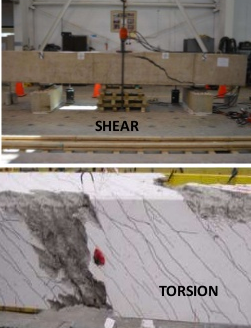
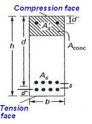
ACI 318-08 Rec Sec. Mx -Q-Torsion Design
Short Description:

Submitted By:
Last Modified
16 Apr 2014
Downloads:
254
Rating:
ACI 318M-11 RC Beam Ledge Design_v0.01_2017-10-11.xlsx
Short Description:

Submitted By:
Last Modified
11 Oct 2017
Downloads:
61
Rating:

ACI 318M-11 RC Bracket and Corbel Design_v0.03_2017-04-10.xlsx
Short Description:
Submitted By:
Last Modified
11 Oct 2017
Downloads:
72
Rating:

ACI 318M-11 Slab Punching stress using RamConcept & calculate of punching shear reinforcement
Short Description:
Submitted By:
Last Modified
11 Oct 2017
Downloads:
114
Rating:

ACI 350 & ACI224R-01 Rectangular Section Flexural Crack Width Control
Short Description:

Submitted By:
Last Modified
29 Sep 2013
Downloads:
204
Rating:
ACI 350.3-06 Seismic Loads for Liquid-Containing Rectangular RC Tank
Short Description:

Submitted By:
Last Modified
29 Sep 2013
Downloads:
221
Rating:

ACI318_08 DEVELOPMENT AND SPLICES OF REINFORCEMENT
Short Description:
Submitted By:
Last Modified
29 Sep 2013
Downloads:
248
Rating:
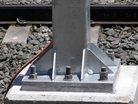
AISC 2016 Base plate calculation _DG-01
Short Description:
The AISC (American Institute of Steel Construction) 2016 specification provides guidelines for the design and construction of structural steel buil...
Submitted By:
Last Modified
21 Jan 2022
Downloads:
119
Rating:

AISC360 05 LRFD Shear Plate bolted connection
Short Description:

Submitted By:
Last Modified
29 Sep 2013
Downloads:
247
Rating:

AISC360-16 LRFD Check of Single Plate Shear connection
Short Description:

Submitted By:
Last Modified
11 Oct 2017
Downloads:
185
Rating:

Anchor Reinforcement
Short Description:

Submitted By:
Last Modified
20 May 2009
Downloads:
961
Rating:


Appendix D - Anchor Bolt Anchorage
Short Description:

Submitted By:
Last Modified
28 Aug 2008
Downloads:
1297
Rating:
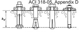
Appendix D - Anchor Bolt Anchorage ACI 318
Short Description:

Submitted By:
Last Modified
24 Oct 2008
Downloads:
1431
Rating:
Application for Generation of Height Span Charts Gable Frame Sheds
Short Description:

Submitted By:
Last Modified
02 May 2010
Downloads:
199
Rating:


ASCE710W - ASCE 7-10 CODE WIND ANALYSIS PROGRAM
Short Description:
ASCE 7-10, 'Minimum Design Loads for Buildings and Other Structures,' is a standard developed by the American Society o...
Submitted By:
Last Modified
15 Mar 2023
Downloads:
1189
Rating:
Base Plate Design (Biaxial Bending) - AISC 360-16 LRFD
Short Description:
The MS-Excel spreadsheet program designed for the analysis of steel column base plates serves as a comprehensive engineering tool catering ...
Submitted By:
Last Modified
10 Nov 2023
Downloads:
202
Rating:
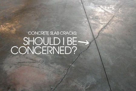
Base Slab and Crack Width
Short Description:
ACI 318-11 Crack Width Calculations For Slab. 1 - Locate the Neutral axis & Calculate section properties: 2 - Check of Concrete &...
Submitted By:
Last Modified
11 Sep 2019
Downloads:
105
Rating:

Beam Investigation.xls
Short Description:

Submitted By:
Last Modified
28 Jul 2012
Downloads:
254
Rating:
BEAMANAL for BOXFRAME
Short Description:

Submitted By:
Last Modified
11 Oct 2016
Downloads:
136
Rating:


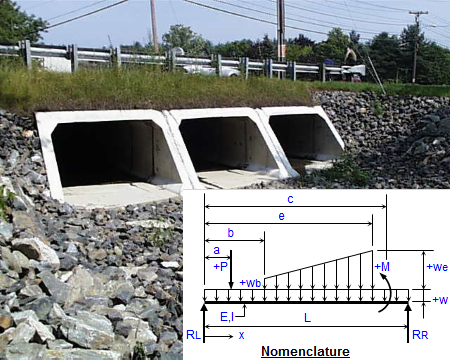
BOXFRAME - CONCRETE BOX FRAME ANALYSIS
Short Description:
Submitted By:
Last Modified
14 Oct 2016
Downloads:
284
Rating:


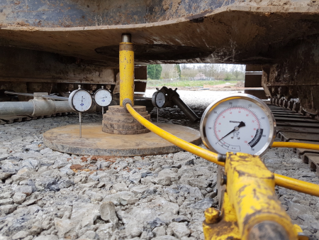
Calculation of Modulus of Subgrade Reaction
Short Description:
Modulus of subgrade reaction or coefficient of subgrade reaction is the reaction pressure sustained by the soil sample under a rigid plate of s...
Submitted By:
Last Modified
26 Oct 2021
Downloads:
123
Rating:


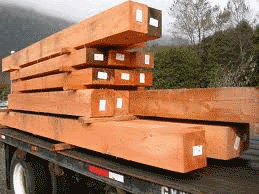
Calculator assessment of timber structures to AS1720
Short Description:
Submitted By:
Last Modified
28 Aug 2010
Downloads:
203
Rating:

Calculator for assessment of coldformed steel structures to AS4600
Short Description:

Submitted By:
Last Modified
03 Dec 2013
Downloads:
264
Rating:

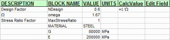
Calculator for assessment of steel structures to AS4100
Short Description:
Submitted By:
Last Modified
16 Feb 2014
Downloads:
220
Rating:
Cantilever Slab Analysis & Design-ACI
Short Description:

Submitted By:
Last Modified
15 Oct 2016
Downloads:
149
Rating:

Capacity Calculation
Short Description:
Submitted By:
Last Modified
23 Mar 2016
Downloads:
125
Rating:
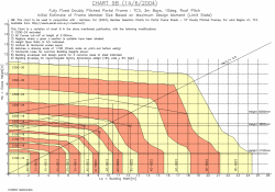
ColdFormed Steel Sheds Australia Height Span Limits of C-Sections
Short Description:

Submitted By:
Last Modified
01 May 2010
Downloads:
72
Rating: